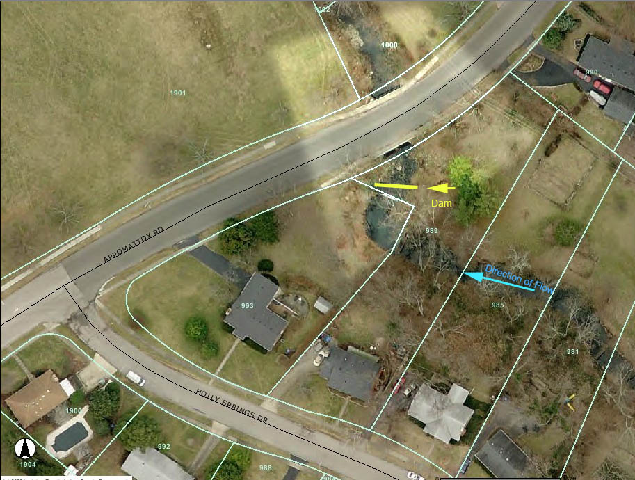
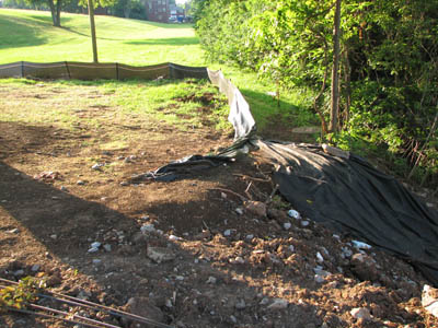
Project Area above,
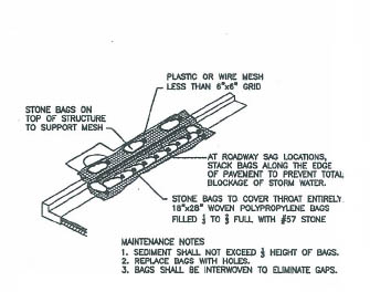
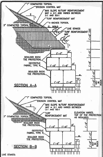
Detail from Design Plans (Sheet 4) below,
Click on image below for close-up


Note: "River Right" and "River Left" refer to the right and left hand banks when looking downstream.
 

Appomattox Road Bridge Replacement
Project Details
Wolf Run Watershed,
Gardenside Area of Lexington, KY.
(Map)

Below are a collection of Images/information detailing design plans for construction sediment and erosion control, in-stream turbidity control and and bank stabilization features for a bridge replacement project over Wolf Run. Collected March, 2008 - October 2008

The purpose of our research is to document contractor performance on design specifications related to construction pollution control and stream bank stabilization in an effort to improve performance on these essential water quality items. 

Friends of Wolf Run has gone on record with this project as being happy with the designs and specifications as done by Strand Engineering and supervised by David Carroll of the LFUCG Division of Water Quality.

Our volunteers in the area observed the work in progress and were impressed by the speed, and professionalism of the contractor (The Allen Company) in getting the project installed under a tight time frame. We have heard no complaints about most of this project's implementation. (Culvert, decking and railing etc...)

But, we do have concerns that essential water quality and bio-engineering components are not being implemented with the same high level of skill and expertise as other aspects of the project.

Our goal with this research and inquiry is to improve construction pollution control, stream bank stabilization and bio-engineering performance by contractors for upcoming projects in the watershed. (Sugar Mill Project on Vaughn's Branch and Beacon Hill Culvert Replacement for example)

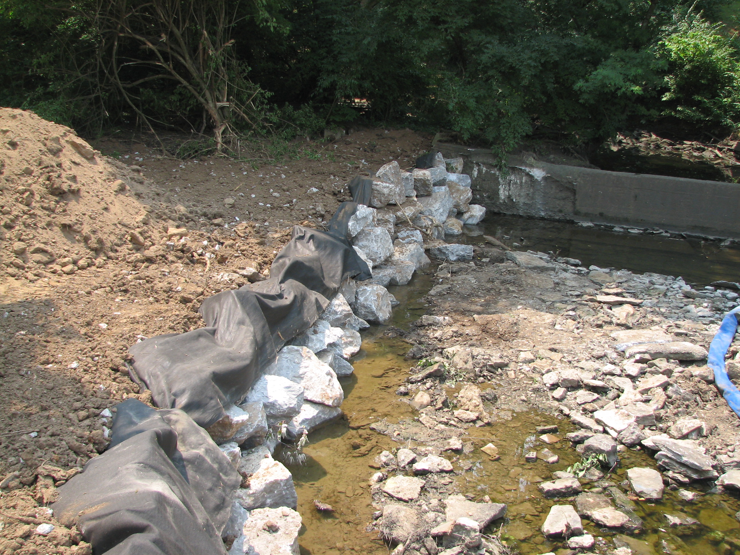
Photos to right LFUCG by Division of Engineering

Project Sediment and Silt Control Features


Right Side looking Downstream:

(Left) Detail from plans (Sheet 4) Showing Downstream River Right construction elements. The plans call for turbidity barriers, stream bank stabilization and silt fencing.


Downstream, River Right during construction after wing wall was in place.


No silt fence, no turbidity barrier seen placed during construction.

After construction, No toe rock, or live stakes or filter fabric bank stabilization seen as detailed in plans above or per plan details on sheet 12(Shown below). (Sod was placed at the top of the bank)


Downstream River Left Plan detail (From page 4)

Showing stream bank stabilization, turbidity barrier and curb inlet protection.


Downstream River Left detail during construction.

No bank stabilization seen per details on page 12 of plans
after construction complete.

Silt fence around construction equipment area seemed to be functioning properly, (actually catching silt during storm events) even though we have heard complaints about its installation.


  Detail of curb inlet protection called for on Sheet 13 of design plans.

None seen during construction by our volunteers. None were present in any construction images provided by LFUCG Division of Engineering.

Silt fence detail 1 showing air gaps below fence
(Screen shot from LFUCG Video)
 

Silt fence detail 2 showing air gaps below fence
(Screen shot from LFUCG Video)


Construction Pollution Control Items Upstream River Right

Specifications on Sheet 4 of the design plans call for 20' X 50' Construction entrance to minimize sediment tracking, in-stream turbidity barriers and bank stabilization.


Construction entrance upstream of culvert on River Right does not appear to have rock and filter fabric as called for in LFUCG 2005 Stormwater Manual section 11.4.6.

no in-stream turbidity barriers seen during construction.

Blue line is pump hose.


Bank Stabilization/Bio Engineering Features.
 

Bank Stabilization Detail from page 12 of plans, calls for placed stone with 1-1 slope finished with 2-1 slope at top. Bank stabilization features were called for both upstream and downstream of project on both sides of stream on Page 4 of plans.

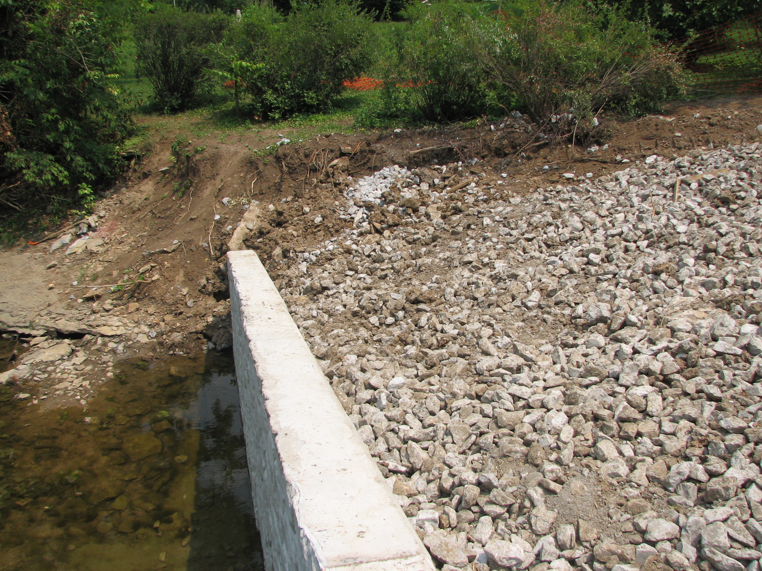
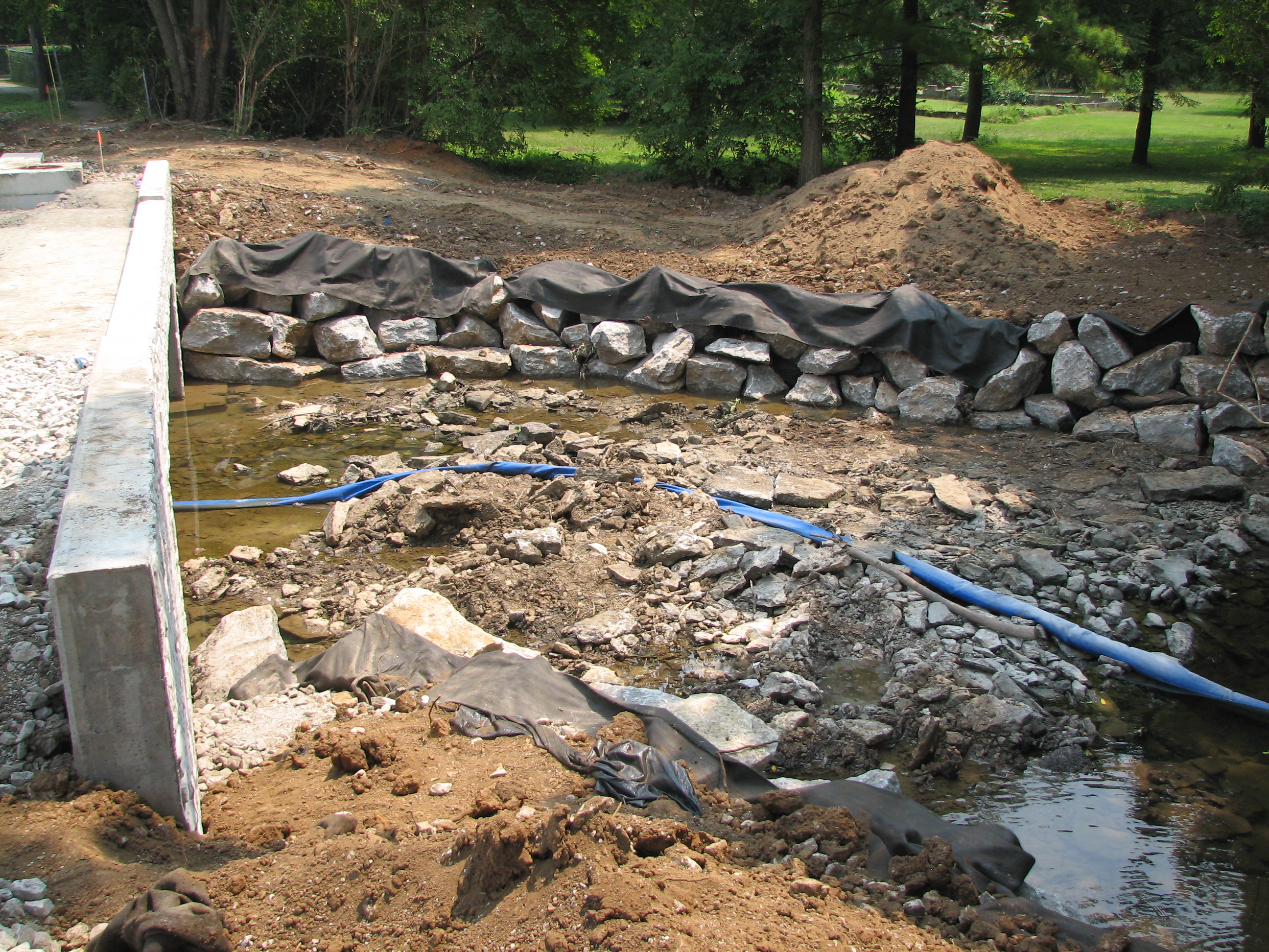
Toe Rock Placement with slope Detail upstream of culvert on river right shows non-uniform size and random placement of rock.
 

Additional detail of toe and ground slope during construction

Note height and near vertical pitch of rock wall.

  Upstream of culvert on River Left during construction
(After storm event blew out back of filter fabric)
 

Upstream River Left after construction complete
showing additional rock placed to shore up bank from the force of current at high water deflected by the upstream dam.


Example of project with similar design specifications (Eastland/Roland Drive, Lexington, KY) note toe height and properly laid back slope of bio-engineered area above rock toe.

A gentile slope is critical for bank stability and for allowing water during bank full events to "spread out" as opposed to being vertically compressed thus increasing current speed, sheer forces and channel scouring.


Live Stakes of Black Willow placed along upstream river right and on street level on upstream river left..

No live stakes seen on downstream side of culvert.
Though Black Williow is a hardwood, Note acceptable species list in detail below. We saw none of the more desireable Button Bush or Red Oser Dogwoods placed on site.

Live Stake Detail from plans on Plan Sheet 12


Finished upstream bank stabilization. (October 2008)

Other Documents


Please (Click) to let us know your comments or corrections on the content of this page
should you find errors in fact or reference.